|
|
Devices << ArduinoDevice << ArduinoDevices << ProtoVoltaicsDevices | Software Overview | Sitemap | Downloads | Developers | Forums |
|
|
Devices << ArduinoDevice << ArduinoDevices << ProtoVoltaicsDevices | Software Overview | Sitemap | Downloads | Developers | Forums |
|
|
ProtoVoltaics Devices on ArduinosHere we describe the ProtoVoltaics devices we support. To learn more about ProtoVoltaics and all their devices, see the http://www.protovoltaics.com website. RTD Shield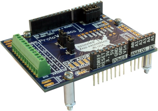
The RTD Shield is a precision ohm meter with additional Arduino software for calculating temperatures of RTD sensors. It is suitable for use with the popular PT100 and PT1000 type sensors. It supports up to 7 two wire sensors, 4 three wire sensors, or 3 four wire sensors. When used in the 3 or 4 wire mode, the shield can compensate for resistances between the sensor and the shield. Based on 3 and 4 wire testing, one can expect accurate resistance readings in the milli-ohm range. For details on the shield see the ProtoVoltaics RTD Shield web page. In the Virtual Wiring System, we use the RTD Shield as a precision ohm meter. To calculate temperatures, we have an additional Device, the RTD to Temperature Virtual Device, which converts RTD resistances to temperatures. The RTD Shield runs on top of our standard Arduinos, and the Arduinos are running Firmata software. Hardware Set UpTo install an RTD Shield into the Virtual Wiring system, decide what kinds of resistance readings you wish to take and configure the RTD Shield's jumpers appropriately. There is a jumper for configuring whether the shield needs to support 2 wire devices or not, and one for configuring what type of device (3 or 4 wire) is on the last set of terminals. There are also 4 jumpers for enabling interrupts to the Arduino; these should be disabled. To disable an interrupt jumper, pull it off entirely or pull it off and slide it onto only one of its 2 jumper pins. Once you have your shield set up, plug it into your Arduino and screw it into place using the supplied standoffs. We found the standoff near the Arduino's SCL pin to be a tight fit - keeping its screws loose until all the standoffs were in place helped us get it into position. As we mentioned, your Arduino should be running Firmata (for more information, see our How To Install Firmata page), as is generally the case for all Arduinos in a Virtual Wiring system. Configuration of the RTD ShieldOne you have your RTD Shield attached to your Arduino and your Arduino's USB port cabled to your Virtual Wiring host, install your Arduino into the Virtual Wiring system. You will need to set the Arduino Script's "i2c_read_delay_micros" parameter to 0, because the RTD Shield requires the Arduino's I2C port be enabled. Once your Arduino is installed , we can configure the RTD Shield. Run the RTDShield Script in the Scripts/Device/Arduino/Devices/ProtoVoltaics Script directory. You'll see a bunch of Script parameters. We'll go over most of these in a general way, and then we'll define each parameter in detail. I2C AddressThe RTD shield is an I2C device with a number of default parameters. The first is the device's I2C address itself. Unless you've added hardware jumpers to the board, its I2C address will be 0x52. If you leave the I2C address parameter as nil, the I2C address will be set to the default. Bias ResistorThe shield has an on board biasing resistor. This resistor is nominally 833.3449 ohms on a rev 1 (shields dated prior to "2-MAY-2014") or 4300.0 ohms on a rev 2 (anything after rev 1). The bias resistor determines the shield's maximum resistance measurement value and much of any reading's absolute accuracy. We've found the shield bias resistors to be stable over time and temperature, but since ours was a 0.5% tolerance resistor, our readings could be off by that much. If we wanted more accurate absolute readings, we'd test our Shield with a 100 ohm 0.01% resistor and calculate the bias resistor value. The "rbias" parameter allows you to override the default (automatically configured to 833.3449 or 4300.0 ohms) with a calculated value and get more absolute accuracy than 0.5%. SamplingThe shield can sample resistances from rates as low as 5 samples per second to as high as 2000 samples per second. If sampling is 20 samples per second or less, the shield has built-in 60Hz filtering. Generally, we sample at 20 samples per second, because it minimizes the amount of time spent sampling while allowing 60Hz filtering. The shield sample rate must be programmed to one of the following values (all are in samples per second): 5, 10, 20, 40, 80, 160, 320, 640, 1000, or 2000. Current and GainWhen measuring resistances, each measurement site (later we'll call these channels) has a programmable current value and gain. Generally, we use 500 micro-Amps (0.0005A) for currents. Larger currents might cause resistive heating (tiny amounts of heating can show up when measuring to mill-ohm accuracies), and smaller currents are more noise prone. We set gains as high as we can while still staying within our measurement range requirements. The larger the gain, the smaller the measurable maximum resistance. The current values must be one of the following values (all are in Amps): 0, 0.000050, 0.000100, 0.000250, 0.000500, 0.000750, 0.001000, or 0.001500. The gains must be: 1, 2, 4, 8, 16, 32, 64, or 128. Channel Parameter NamesWhen configuring the RTD sensor, we define which sensor inputs are in use. The RTD Shield documentation (and the board itself) defines inputs as either 2 wire, 3 wire or 4 wire, and each of the possible sensor inputs are called "channels". 2 wire inputs have channels 1-7, 3 wire inputs have channels 1-4, and 4 wire inputs have channels 1-3. We used the same terminology when naming our sensor input parameters. For example, we call the 3 wire configuration parameter for channel 2, "w3ch2". The same is true for all channel parameters. They all are of the form w<number of wires>c<channel number> where the <>s represent the number defined inside them. Channel 5 for a 2 wire configuration would be w2ch5. Channel Parameter CheckingThe RTD Shield does not allow sharing of inputs between channels, so only some of the channel parameters can be active at one time (you can't have w3ch4 and w4ch3 both active, for example). In addition, certain wire/channel combinations will rule out others. These constraints are explained in the documentation. They are also checked in software when configuring the RTDShield Device. Channel Parameter ValuesThe w<number of wires>c<channel number> parameter names take a string with 3 comma separated values. These define the channel's terminal name, the test current used when measuring resistance, and the gain. The first value in the string is the channel's terminal name, the 2nd is the test current (in Amps), and the last is the gain for that channel. Note: sample rate is a global parameter which applies to all the channels; current and gain are programmable on a per channel basis. As an example, if the w4ch2 parameter were set to How to Choose your GainThe maximum measurable resistance is determined by the bias resistor (~833 or ~4300 ohms) and the gain. In 4 and 2 wire channels, the maximum measurable resistance is: In 3 wire channels, the maximum measurable resistance is: Generally, you want the gain to be as high as you can get it and still be within your resistance measurement range. As an example, our "outdoor_temp" 4 wire channel has a gain of 16. With a bias resistor of 833 ohms, it could measure resistances from 0 to 52 ohms. With a bias resistor of 4300 ohms, it could measure resistances from 0 to 269 ohms. Configuration ParametersThe configuration parameters for the RTD Shield are as follows:
A Configuration ExampleHere we will set up three 4 wire sensors. Their output values will show up on Arduino terminals called sense1, sense2, and sense3. They'll be sampled at 20 samples per second, and the RTD Shield is connected to an Arduino with ID, "arduino". All 3 sensors will have a sense current of 500 micro-Amps and a gain of 16 (by the way, these values work out pretty well for PT100 sensors). We're tweaking the bias resistor from the default (4300 ohms) to 4291 ohms. We run the RTDShield Script with the following parameters:
|
Catalina Computing, LLC.Copyright © Catalina Computing, LLC. (2013-2018) 
|
Page last updated: Thu Jul 16 16:17:40 2015 (UTC) |