|
|
Wires << WiresPunchblockView | Software Overview | Sitemap | Downloads | Developers | Forums |
|
|
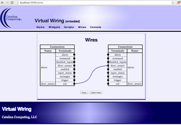
Wires Page: Punchblock View
The Punchblock view is meant to simulate a wiring punchblock. As in a real punchblock, there are two terminal strips, each with a set of terminals arranged vertically. Each terminal strip has all the terminals in the system. The terminals are grouped by device and the devices are arranged alphabetically by their device IDs. Within each device, terminals are arranged alphabetically by name. Adding WiresConnections between device terminals are made by dragging a "wire" from a terminal in the left terminal strip and dropping it on a terminal in the right terminal strip. (Terminals are those round balls at the edges of the terminal strips.) Dragging is accomplished by doing a left mouse click on a the left terminal, holding it while moving the mouse (you should see a wire following the mouse), and releasing the mouse when it's on top of the desired right terminal. In some views (for as yet unexplained reasons), one needs to click on a terminal just to the left of its center to get a wire started. Try this if your can't get a wire started. Deleting WiresWires are deleted by left clicking on a wire. One can click anywhere on a wire. After clicking on a wire, one gets a dialog box describing the left and right terminal connections of the wire asking if it's OK to delete the wire. If the connections look right, you've clicked on the correct wire. Click the "OK" in the dialog box to delete the wire. If you've clicked on the wrong wire, click on the "Cancel" in the dialog box. At the bottom of the Punchblock view page, next to the "Table View" button, there's a button marked "Clear". If you click on this, all the wires in the system will be deleted. This button can save a lot of individual deletion operations when one is rewiring a mass of wires. 2 Possible Punchblock Wires for Every ConnectionEach terminal strip in the Punchblock view has all the terminals in the system. As a result, there are two equivalent wires for each possible connection. As an example, assume we need a connection between terminal 1 on device A to terminal 1 on device B. One could draw a wire from left punchblock terminal A:1 to right punchblock B:1, or one could draw a wire from left bunchblock terminal B:1 to right punchblock A:1. From a Virtual Wiring perspective (or an electrical one), these two wires are equivalent. One could draw either one or both, and the system would function identically. So why do we care that there are two possible connections? Firstly, each time one draws a Virtual Wire, one has a choice of which endpoint to start with. Secondly, when one wants to delete a Virtual Wire, one needs to look in two places. So how to choose a start point? Generally, when one wires a system, there is a sense of things flowing from outputs to inputs, so it makes sense to wire things this way. If A:1 is an output controlling input B:1, start with terminal A:1. Though it makes no difference from a functional point of view which wire you start with, later, if you want to find the wire, knowing it how you picked your start point will save you some time. You can use any heuristic you wish for picking Virtual Wiring start points. Being consistent will make it easier for you to find wires when/if your system gets big. |
Catalina Computing, LLC.Copyright © Catalina Computing, LLC. (2013-2018) 
|
Page last updated: Fri Apr 26 01:04:26 2013 (UTC) |