Programming your Omniwheel Bot
Want to change the way your bot responds to joystick commands? Support new hardware? Just curious? Here we will explain how your bot program works. The actual motor control code is very small, so it's easy to understand and modify.
The program for your omniwheel bot is included in Virtual Wiring Software releases 1.6 and later. It's called "vd_omniwheel_bot_controller.rb" and it's in the "programming" directory in the "virtualizer" directory. We have also have it on line here, so you can easily reference it while you read this article. It's written in Ruby, a popular high level language.
The bot program is written as a Virtual Wiring Virtual Device. If you are not familiar with Virtual Devices, you may want to read more about them by following the link. We'll touch on the Virtual Device specific parts of the code, but we'll be focusing on the bot related code. If you just want to change how your bot motors are controlled, the Motor Control section may be all you need to read.
The Wiring
It's hard to talk about the bot program without referencing Virtual Wiring. The bot program is just code, and it doesn't do anything unless it gets connected to your bot's motors and your joystick. To connect your bot code to your hardware, we use Virtual Wires.
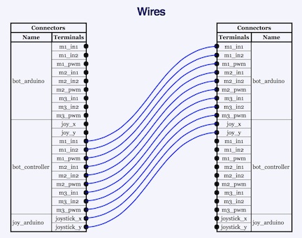
The bot project has 3 basic Devices - an Arduino controlled bot, an Arduino sensed joystick, and a Virtual Device bot controller. The bot's Arduino has a set of terminals for controlling motors, and the joystick's Arduino has a set of terminals for communicating joystick position. We "wire" the Arduino terminals to the Virtual Device created by our bot program, so our Virtual Device reads our joystick and controls our bot.
Here we show the wiring created by our project's startup script. There are two diagrams: one for projects using the Adafruit motor shield and the other for projects using the Wicked Device shield. In the diagrams, you can see our Devices - "bot_arduino", "joy_arduino", and "bot_controller".
Bot Wiring - Adafruit Shield
 Bot Wiring - Wicked Device Shield
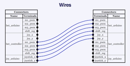
The way we've drawn the wires, you can see the way signals flow: from the joy_arduino, to the bot_controller, and lastly from the bot_controller to the bot_arduino. The terminals on the bot_controller are defined in the bot program.
Program Methods
Here we'll go over the methods in the bot program.
The Motor Control Method - set_speed
The motor control method is probably the most interesting part of our bot program; it's the code that controls the bot's motors. Motor control is accomplished by a single method called adafruit_set_speed, if you have an Adafruit motor shield, or wickeddevice_set_speed, if you have a Wicked Device motor shield. Both methods create motor commands for their motor shield, and both method's outputs get wired directly to our bot_arduino. Both methods take a joystick position coordinate as an input parameter.
Code Walk Through
The set_speed methods for both shields works as follows.
First, they assume the joystick is at rest (coordinate [0,0]) and generate default values for stopping the bot. There is a test to see if the joystick is moved off center (if x != 0 || y != 0). If the joystick is off center, its [x,y] coordinate is converted into an angle (in radians) and a magnitude (by the get_angle_and_mag method). A magnitude/angle pair is sometimes called a Polar Coordinate. If the joystick is off center, its position is then projected onto the direction vector for each of the 3 motors; we define the 3 motor directions as the angles 0, 2Pi/3, 4Pi/3 radians. The Projected value determines how much relative velocity each motor needs to supply to go in the joystick direction. If the joystick is off center, its displacement magnitude scales all of the projected velocities (all are multiplied by mag). If the joystick is off center, all the projected velocities are used to create values for the motor shield. All the current motor shield values are compared with the last values sent. If a value is different, it gets sent; if it is the same, the value is not sent. If there are a lot of joystick direction changes in a short time, testing for change minimizes the amount of data that gets sent to the bot. All the motor shield values get saved for the next comparison.
When you look at the actual code, you'll see that all the shield values are being sent by a method called generate_event. If you read about Virtual Devices, you'll learn that this method causes values to be sent to the Virtual Device's terminals.
A Note on How the Adafruit Motor Controller Works
The Adafruit shield has a PWM chip with 3 outputs for controlling each motor. 2 of the 3 outputs control the motor's direction and are set to on/off or off/on depending on the desired direction. The third output is pulse width modulated (PWM) with values from 0 to 100 depending on the desired motor speed (stopped is 0, full on is 100). The 3 outputs are referenced in the code with suffixes in1, in2 and pwm; their prefixes are m1, m2, and m3, for each of the 3 motors (e.g. motor 2's PWM output is called "m2_pwm").
A Note a How the Wicked Device Motor Controller Works
The Wicked device shield has a single PWM output per motor, and a separate control register with bits for controlling motor direction. Setting a direction bit causes a motor to spin one direction, clearing the bit causes it to spin in the opposite direction. Control register bits 13, 11 and 9 control motor direction for motors 1, 2, and 3. As with the Adafruit shield, the PWM motor outputs take values from 0 to 100, and a 0 value turns off a motor and a 100 value turns a motor full on. The actual control register hardware, a shift register, gets written with the value in the shift_reg variable. The 3 PWM output names have a "pwm" suffix and the prefixes m1, m2, and m3 (e.g motor 3's PWM output is called m3_pwm).
normalize Method
The normalize method takes a raw joystick displacement value, [x,y], and returns a centered and properly sized displacement. Displacements are [x,y] values where the values are in the range from -100 and +100. The first time the method gets called, it assumes the joystick is at zero displacement, and the initial raw displacement becomes its at-rest displacement. The method has been tailored to work with a Grove Thumb Joystick, and needs a x4 fudge factor to get the joystick values to generate values over the full output range.
Define Terminals Methods
These define the terminals of your bot controller - there are 2 methods. One defines terminals for a controller connected to an Adafruit shield, and the other defines terminals for a controller connected to a Wicked Device shield. They are called adafruit_terminal_dids and wickeddevice_terminal_dids. Depending on the type of bot shield you have, one of these methods will get named (using an alias) terminal_dids. All Virtual Device terminals are defined by their terminal_dids method (see Creating Virtual Devices).
You will want to modify these methods when you wish to add or remove terminals on your bot controller.
Shield Init Methods
There are 2 shield init methods - adafruit_shield_init and wickeddevice_shield_init. These allow the program to work with either an Adafruit motor shield or a Wicked Device motor shield. They name (alias) the generic set_speed and terminal_dids methods to be either Adafruit methods or the Wicked Device methods.
bot_thread Method
The bot_thread method creates a Thread for running the bot. The thread waits for joystick values (by waiting on a queue) and uses the values to control the bot. For each joystick value, it normalizes it and calls the set_speed method. The set_speed method is an aliased Adafruit or Wicked Device method, depending on whether adafruit_shield_init or wickeddevice_shield_init was called.
We create a separate thread for running the bot, because sending commands to a motor shield can take a little while, and we don't want to delay the main thread.
respond_to_inputs Method
The respond_to_inputs method is a standard Virtual Device method that gets called when a Virtual Device's terminals receive new values. In the bot program, we filter out all values that are not joystick values, and we queue the remaining values into a queue polled by our bot_thread. We queue rather than control the motors directly, because this method is called by our main thread, and we don't want to slow this thread down.
get_angle_and_mag Method
The get_angle_and_mag method takes a joystick coordinate (an [x,y] value), and computes the angle and amount of joystick displacement. It also makes a slight correction to the computed value to allow for the fact that a Thumb joystick's maximum displacement values follow a square and not an ideal circle (where all maximum displacement values would be equidistant from the center).
controller_init Method
The controller_init method does basic setup of the bot program. It creates the queue used by the bot program's thread, initializes the program's speed variables, and it creates the bot program thread.
|