|
|
Devices << XBeeDevices << XBeeDIOAdapterInstallation | Software Overview | Sitemap | Downloads | Developers | Forums |
|
|
Devices << XBeeDevices << XBeeDIOAdapterInstallation | Software Overview | Sitemap | Downloads | Developers | Forums |
|
|
XBee Digital I/O Adapter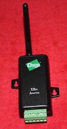
The Digi Digital I/O Adapter is programmable digital interface. It has 4 screw terminals for control and monitoring of digital devices, and 2 screw terminals for providing power. Screw terminals 1-4 can be either outputs or inputs, terminal 5 is a dedicated ground terminal, and terminal 6 can provide up to 50mA of current at 12 volts (useful for many 12 volt sensor devices). Full control of the 12 volt power output, the mode of each I/O pin, as well as sensing and output values are provided over the wireless interface. The device can run from an external power supply or from an internal battery. The Virtual Wiring system supports the Digital I/O device when it is using an external supply; it does not support the device when it is running from a battery. For a complete description of the Digital I/O Adapter, consult the Digi manual. XBee Digital I/O Terminals
The Virtual Wiring DigitalIO Device represents the Digital I/O Adapter device within the Virtual Wiring System. The Device has 4 input and 4 output terminals. Depending on the configuration of the Digital I/O Adapter device, some or all of the 8 terminals are active. The 4 input terminals control the output state of the 4 screw terminals. They are called "1", "2", "3" and "4" and take either XBee Digital I/O Device InstallationTo install a DigitalIO Device, the device must first be joined into an existing XBee network (which the Virtual Wiring system is a part of). Once joined, create a DigitalIO Device by running the DigitalIO Script. The parameters for the DigitalIO Script are:
ExampleTo add a DigitalIO Device with ID "dio", screw terminals 1 & 2 inputs, screw terminals 3 & 4 outputs, 12 volt power, and network address 0013a200406b0263 to a system which is wired to a Coordinator Device at port_location "/dev/ttyUSB0", run the DigitalIO Script with the following parameters: Note: the port_location parameter can be set to nil, if the system owns only one XBee network. |
Catalina Computing, LLC.Copyright © Catalina Computing, LLC. (2013-2018) 
|
Page last updated: Mon Jan 12 17:02:27 2015 (UTC) |
